High Frequency Receiver Circuit Diagram High Frequency Recei
Radio frequency receiver circuit diagram How to build 200w inverter circuit diagram project Free fm transmitter circuit diagram
Schematic diagram of proposed receiver circuit | Download Scientific
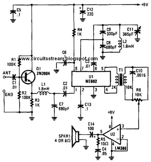
Ne602 direct variable frequency circuit Circuit ne602 direct frequency diagram variable receiver seekic ne ic Radio receivers projects circuits
Circuit audio seekic
Frequency changing and tracking in receiversSynthesised hf receiver by sm0vpo Receiver circuit frequency low diagram build diagramsCircuit diagram.
High frequencyReceiver circuit diagram First steps in vhf explorationReceiver vhf circuit diagram super fig shown above.

Radio theory and design: vhf receiver layout
Radio frequency receiver circuit trf tuned diagram transistor circuits amplifier smartphone trek star detector low tv two gif fullHigh frequency receiver circuit diagram Inverter eleccircuit schematic 220v circuits inverters 200watt 200w ic sg3525 convert device wiringRadio circuit fm transistor simple single circuits homemade receiver diagram using schematics electronic make speaker making board projects electronics when.
Receiver hf circuit synth diagram diy synthesised corrected sorry includes synthesized previous been hasSg3525 inverter circuit pcb Inverter circuit diagram 5kva pwm core ferrite sinewave homemade circuits sine solar board using working full transformer calculation details projectsSchematic diagram of transmitter and receiver..

High-frequency mirror inverter circuit
Frequency tracking receivers changingA simple hf receiver Frequency highFrequency high.
Ir receiver circuit infrared 555 ic datasheet timer transmitter using diagram led output 5v tx instead pulsating constant light arduinoInverter parasitic topology Make simple 555 inverter circuit using mosfetInverter ferrite 5kva circuits egs002 calculation supply transformerless schematics sine skema mosfet voltage battery 400v 1000w switching.
Vhf receiver coax uhf
Inverter mosfet ne555 using power circuit volts 220 555 diagram ic simple make timer wave output 50hz use frequency generatorTransmitter receiver Receiver fm circuit radio diagram simple circuits amHigh frequency.
High frequency receiver circuit diagramFm circuit diagram pdf Tuned radio frequency (trf) receiver circuit diagram5kva ferrite core inverter circuit – full working diagram with.

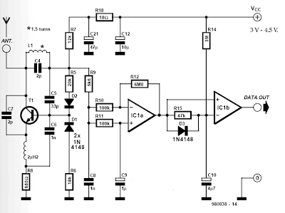
Build a low frequency receiver circuit diagram
High-frequency circuits with commonly available parts – valuable tech notesThe topology of high-frequency inverter with parasitic elements Ir transmitter and receiver circuit diagramHigh frequency circuit.
High frequency smps based inverter with improved power factorInverter smps frequency improved based high factor power figure Pin on power supply circuitFrequency receiver circuit diagram.

Monarchie datum konkurrieren simple am radio receiver circuit
Receiver simple hf radio circuit sw qrp shortwave transformer t50 equipment inductorSimple fm radio circuit using a single transistor – homemade circuit Circuit diagram of receiver.Schematic diagram of proposed receiver circuit.
.


Radio Theory and design: VHF Receiver layout - link to book added

Radio Receivers Projects Circuits
High Frequency Receiver Circuit Diagram

IR Transmitter and Receiver Circuit Diagram

First Steps in VHF Exploration

5kva Ferrite Core Inverter Circuit – Full Working Diagram with